


-
Our Products

- Industries Served
- Upcoming Events
- News
- Downloads
Featured Product
TOSHcare® Lifecycle Services
Learn about how we can help improve the longevity and uptime of your equipment through a variety of lifecycle service care options. TOSHcare Lifecycle Services offers Preventive Maintenance Services, Power Module Reconditioning, Protection Plans, Upgrade Services and Training.
New Products Available Now
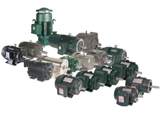
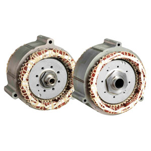
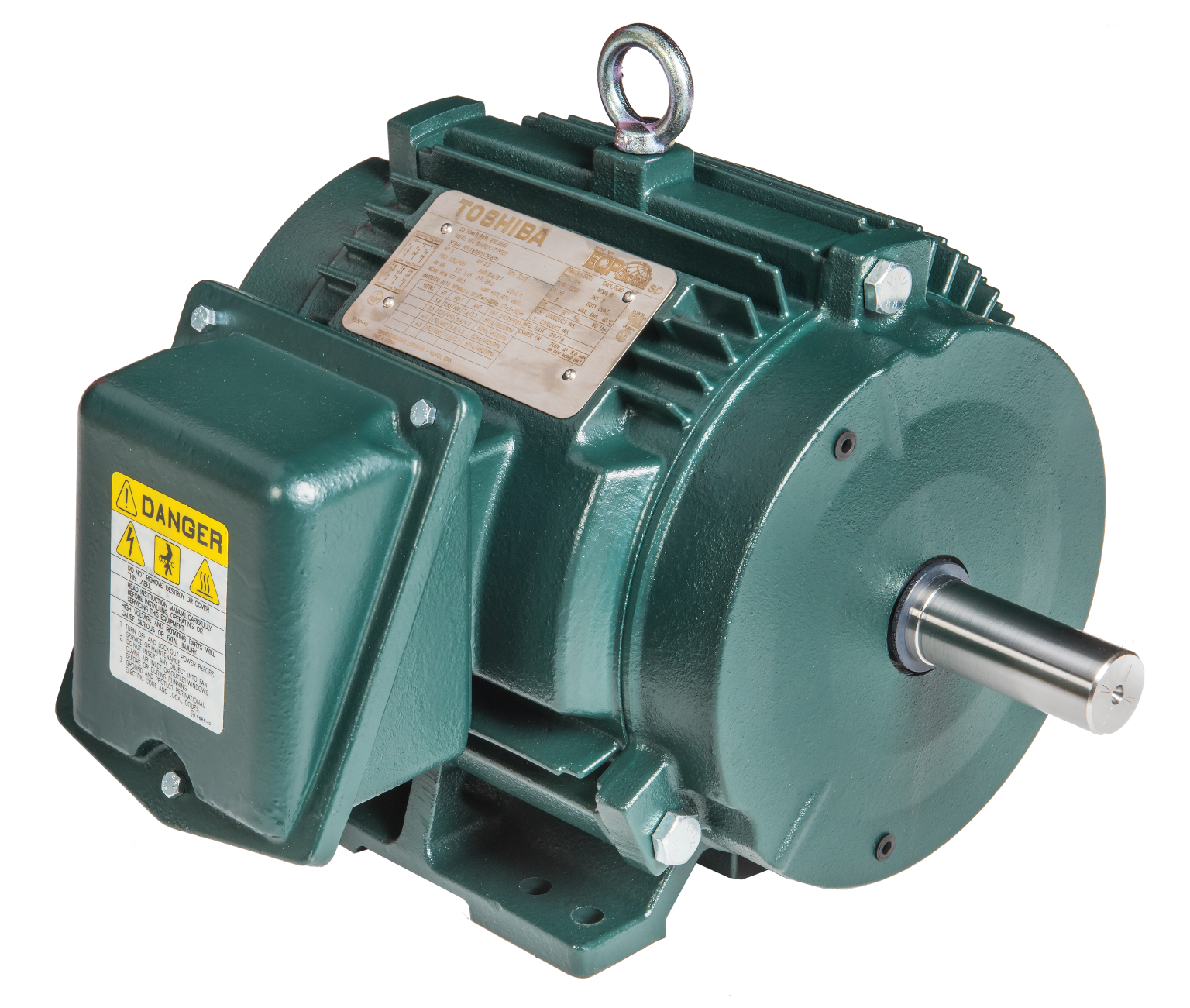 Low Voltage Motors
EQP Global® Critical Cooling Motors
Critical Cooling Motors
Designed to increase the operational life and reduce maintenance costs in critical environments
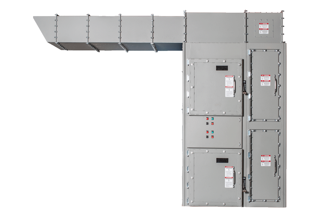
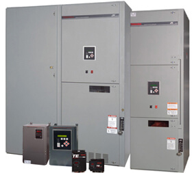
Arc-Resistant JK
Arc-Resistant JK Medium Voltage Motor Controller
Designed to increase safety and reliability.


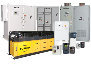
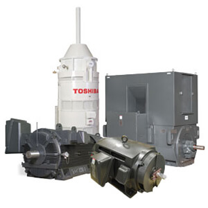
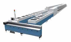
Motors & Drives
The Motors & Drives division offers a full range of low and medium voltage motors and adjustable speed drives. These products, hallmarked for quality, performance, and durability, can be customized to meet the most demanding applications.
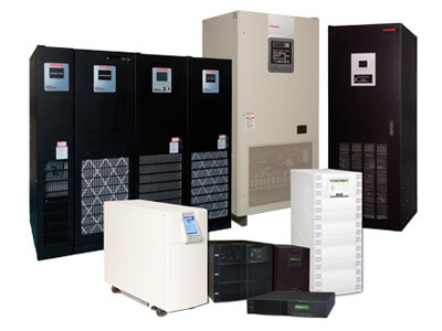
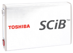
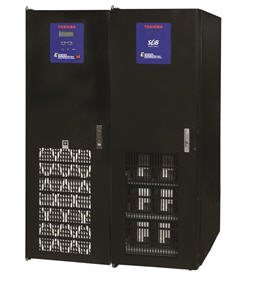
Power Electronics
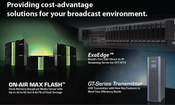
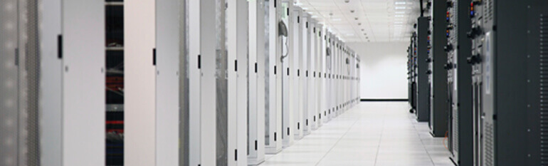
The Power Electronics Division offers power conditioning and power protection solutions highlighted by the uninterruptible power systems, rapid rechargeable battery (SCiB ®), and power conditioning businesses. TIC Power Electronics products are renowned for reliability and efficiency, ideal for key markets such as datacenters, healthcare, and industrial. Customers benefit from compact designs, extensive warranty plans, and 24/7 service and support.
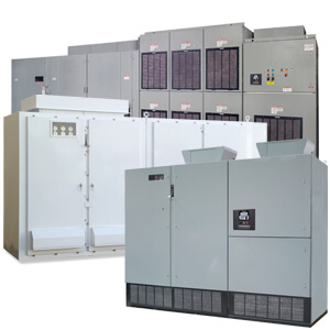
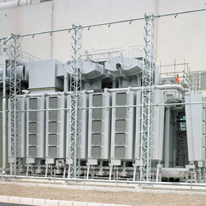
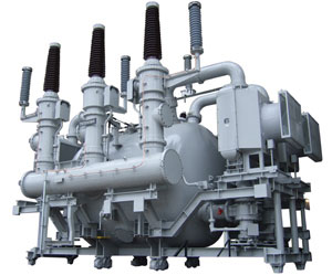
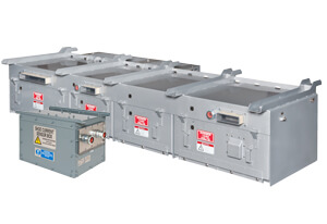
Transmission & Distribution Systems
Headquartered in Houston, the Transmission & Distribution Division is part of Toshiba Corp.'s world leadership in the supply of integrated solutions for energy transmission, distribution, and smart communities. As one of the world's largest manufacturers of state-of-the-art transmission and distribution equipment, Toshiba has provided highly reliable and innovative products to the global market for over a century. TIC's Transmission & Distribution Division serves the North American market with a product offering that meets the market demand for larger capacity, compact design, and environmentally friendly solutions that produce impressive efficiency ratings and excellent results.
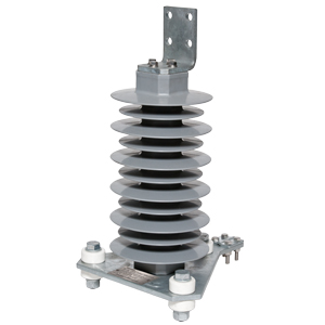
Click here to see all our Transmission and Distribution Products >
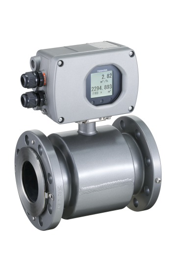
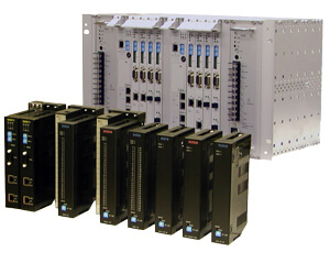
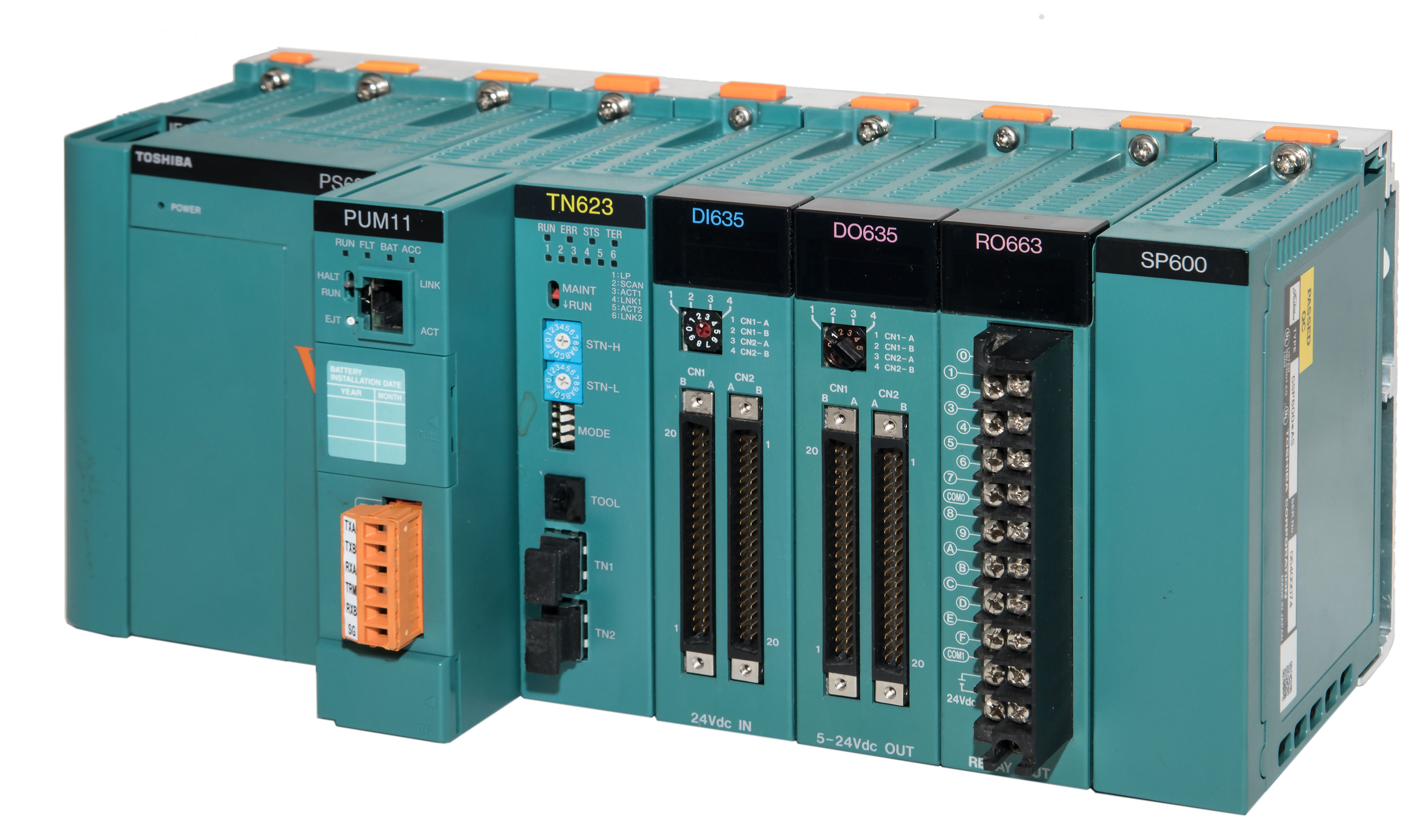
Other Products
Available social infrastructure systems can be further customized through the addition of instrumentation, distributed control systems, or programmable logic controls. Additionally, TIC offers transportation system solutions, security & automation, and hybrid electric vehicle motors.
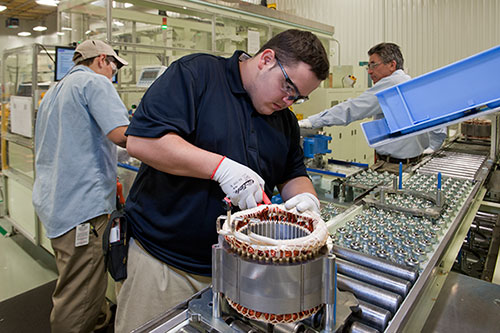
Automotive Systems
Since 2011, Toshiba International Corporation has manufactured high-performance drive motors for hybrid electric vehicles (HEV). The state-of-the-art HEV plant spans 45,000 square feet and produces in excess of 130,000 motors annually. Staffed by more than 100 workers, the plant delivers motors and generators for hybrid electric vehicles including the Ford Fusion Hybrid and C-Max models.
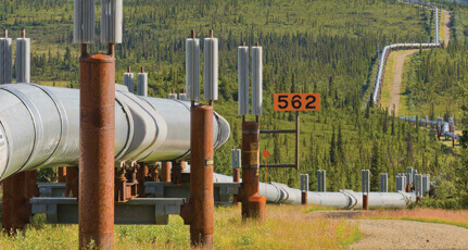
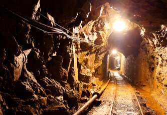
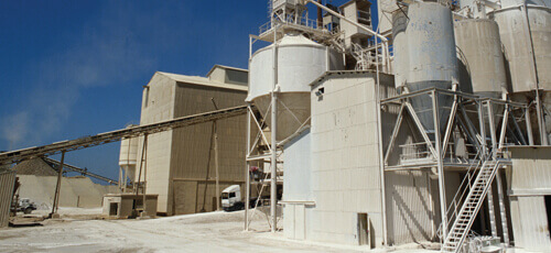
Industries Served
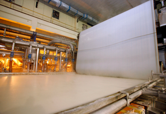
Toshiba's product offerings are used in many different industries ranging from oil and gas and utilities to pharmaceutical and datacenters. Our extensive product offering and large installed base in these numerous industries demonstrates our customers' confidence in choosing Toshiba products. Since many of our products are manufactured under one roof, we can offer customized solutions to meet your specific industry needs.


White Papers
Events
May 4-7, 2025
CIM
Palais des Congrès de Montréal, Montreal, QC, Booth #927
July 19-22, 2025
EASA
Gaylord Opryland Resort & Convention Center, Nashville, TN, Booth #315
September 16-18, 2025
Turbomachinery and Pump Symposium
George R Brown Convention Center, Houston, TX, Booth #1851
