

Monitoring the Operation Status
Accessing Monitor Screen from Keypad
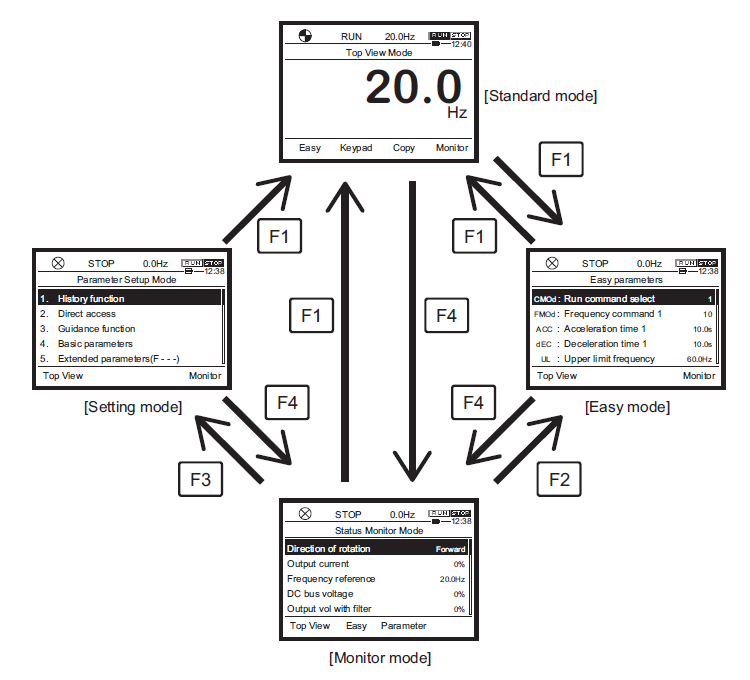
Access the monitor screen from the default keypad screen by pressing the F1 function key one time. If not on the default keypad screen, please follow graphic below to access the monitor screen.
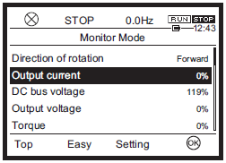
Monitor Mode Displayed Item Descriptions:
Direction of rotation Forward or Reverse inverter output direction.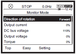
Selected monitored items 1 to 8 [F711: Monitor mode 1 display] to [F718: Monitor mode 8 display]
By default:
- Output current
- Input voltage (DC detection)
- Output voltage
- Torque
- Input power
- Output power
- Inverter load factor
- Motor load factor
- May be changed to monitor other items at parameters [F711] to [F718] shown at the end of this page.
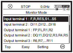
Input/output Terminals
Displays the ON/OFF status of the following input/output terminals.
- Input terminal 1 (F, R, RES, S1...S4, S5)
- Input terminal 2 (DI11, DI12...DI16)
- Output terminal 1 (FP, FL,R1, R2)
- Output terminal 2 (DQ11, DQ12, R3, R4, R5)
- Output terminal 3 (R6, R7...R11)
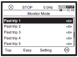
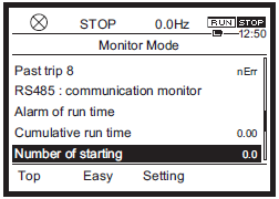
Past trip 1 to 8
Past trip 1 is the record of the latest trip, Past trip 8 is the record of the oldest trip. If no trip information exists, “nErr” is displayed.
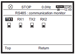
Communication status
RS485 communication connector 1 and 2 status.
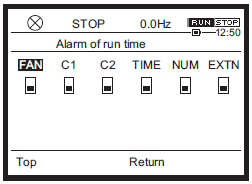
Parts replacement alarm
Displays replacement alarms of the cooling fan, capacitor, etc.
Cumulative run time
Inverter cumulative run time is display. The display unit is 100 hours and the minimum value 0.01 Is equal to 1 hour. To clear the value, set parameter [tyP: Default setting] to "5: Clear cumulative run time."
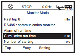
Number of starting
The number of inverter starts is displayed. The display unit is one time and the maximum value is 9.99 million times. In the case of an LED display extension panel, the display unit is 10000 times and the minimum value 0.1 is equal to 1000 times. To clear the value, set [tyP: Default setting] to "12: Clear cumulative run time."
| Setting Value | Function Name | Display Unit | Settings for [F711: Monitor mode 1 display] to [F718: Monitor mode 8 display] | |||||||
| 0 | Output frequency | 0.1 Hz | ||||||||
| 1 | Frequency command value | 0.1 Hz | ||||||||
| 2 | Output current | 1%/[F701] setting | ||||||||
| 3 | Input voltage (DC detection) | 1%/[F701] setting | ||||||||
| 4 | Output voltage | 1%/[F701] setting | ||||||||
| 5 | Stator frequency | 0.1 Hz | ||||||||
| 6 | Speed feedback frequency (real time) | 0.1 Hz | ||||||||
| 7 | Speed feedback frequency (1-second filter) | 0.1 Hz | ||||||||
| 8 | Torque | 1% | ||||||||
| 9 | Torque command | 1% | ||||||||
| 10 |
Output frequency during
run.
Frequency command value during stop. |
Hz/free unit | ||||||||
| 11 | Torque current | 1% | ||||||||
| 12 | Exciting current | 1% | ||||||||
| 13 | PID feedback value | 0.1 Hz | ||||||||
| 14 | Motor overload factor (OL2 data) | 1% | ||||||||
| 15 | Inverter overload factor (OL1 data) | 1% | ||||||||
| 16 | Braking resistor overload factor (OLr data) | 1% | ||||||||
| 17 | Braking resistor load factor (%ED) | 1% | ||||||||
| 18 | Input power | 0.1 kW | ||||||||
| 19 | Output power | 0.1 kW | ||||||||
| 20 | Input cumulative power | [F749] setting | ||||||||
| 21 | Output cumulative power | [F749] setting | ||||||||
| 22 | Fixed output 1 | - | ||||||||
| 23 | Fixed output 2 | - | ||||||||
| 24 | Terminal RR input value | 1% | ||||||||
| 25 | Terminal RX input value | 1% | ||||||||
| 26 | Terminal II input value | 1% | ||||||||
| 27 | Motor speed command | - | ||||||||
| 28 | Terminal FM output value | 1 | ||||||||
| 29 | Terminal AM output value | 1 | ||||||||
| 30 | ||||||||||
| 31 | Communication data output | - | ||||||||
| 32 | Slot A option CPU version | - | ||||||||
| 33 | Slot B option CPU version | - | ||||||||
| 34 | Motor load factor | % | ||||||||
| 35 | Inverter load factor | % | ||||||||
| 36 | Inverter rated current | A | ||||||||
| 37 | Inverter rated current (with carrier frequency correction) | A | ||||||||
| 38 | Actual carrier frequency | kHz | ||||||||
| 39 | Slot C option CPU version | - | ||||||||
| 40 | Embedded Ethernet CPU version | - | ||||||||
| 41 | Terminal FP pulse train output value | pps | ||||||||
| 42 | ||||||||||
| 43 | Terminal FM/AM gain setting value | - | ||||||||
| 44 | Terminal AI4 input value | 1% | ||||||||
| 45 | Terminal AI5 input value | 1% | ||||||||
| 46 | My function monitor output 1 | - | ||||||||
| 47 | My function monitor output 2 | - | ||||||||
| 48 | My function monitor output 3 | - | ||||||||
| 49 | My function monitor output 4 | - | ||||||||
| 50 | ||||||||||
| 51 | ||||||||||
| 52 | ||||||||||
| 53 | ||||||||||
| 54 | ||||||||||
| 55 | ||||||||||
| 56 | ||||||||||
| 57 | ||||||||||
| 58 | ||||||||||
| 59 | ||||||||||
| 60 | ||||||||||
| 61 | ||||||||||
| 62 | PID result frequency | 0.1 Hz | ||||||||
| 63 | PID set value | 0.1 Hz | ||||||||
| 64 | Light-load high-speed switching load torque | 1% | ||||||||
| 65 | Light-load high-speed torque during constant speed run | 1% | ||||||||
| 66 | Pattern operation group number | 0.1 | ||||||||
| 67 | Pattern operation remaining cycle number | 1 | ||||||||
| 68 | Pattern operation preset speed number | 1 | ||||||||
| 69 | Pattern operation remaining time | 0.1 | ||||||||
| 70 | Inverter rated voltage | 1 | ||||||||
| 71 | Motor speed (estimated value, Max. 32700 min-1) | 1 | ||||||||
| 72 | Communication option receiving counter | 1 | ||||||||
| 73 | Communication option abnormal counter | 1 | ||||||||
| 74 | ||||||||||
| 75 | ||||||||||
| 76 | Terminal S4/S5 pulse train input value | 0.10% | ||||||||
| 77 | My function COUNT1 | 1 | ||||||||
| 78 | My function COUNT2 | 1 | ||||||||
| 79 | Dancer control PID result frequency | 0.1 Hz | ||||||||
| 80 | Embedded Ethernet Transmission counter | - | ||||||||
| 81 | Embedded Ethernet Receiving counter | 1 | ||||||||
| 82 | Embedded Ethernet Abnormal counter | 1 | ||||||||
| 83 | Connected option number | 1 | ||||||||
| 84 | My function COUNT3 | 1 | ||||||||
| 85 | My function COUNT4 | 1 | ||||||||
| 86 | My function COUNT5 | 1 | ||||||||
| 87 | ||||||||||
| 88 | ||||||||||
| 89 | ||||||||||
| 90 | Cumulative power ON time | 100 hours | ||||||||
| 91 | Cumulative cooling fan run time | 100 hours | ||||||||
| 92 | Cumulative run time | 100 hours | ||||||||
| 93 | Cumulative overcurrent time | 100 hours | ||||||||
| 94 | ||||||||||
| 95 | Pump 0 run time | 100 hours | ||||||||
| 96 | Pump 1 run time | 100 hours | ||||||||
| 97 | Pump 2 run time | 100 hours | ||||||||
| 98 | Pump 3 run time | 100 hours | ||||||||
| 99 | Pump 4 run time | 100 hours | ||||||||
| 100 | Number of starting | 10000 times | ||||||||
| 101 | Number of Fwd starting | 10000 times | ||||||||
| 102 | Number of Rev starting | 10000 times | ||||||||
| 103 | External equipment counter | Time | ||||||||
| 104 | ||||||||||
| 105 | Pump 5 run time | 100 hours | ||||||||
| 106 | Pump 6 run time | 100 hours | ||||||||
| 107 | Pump 7 run time | 100 hours | ||||||||
| 108 | Pump 8 run time | 100 hours | ||||||||
| 109 | Pump 9 run time | 100 hours | ||||||||
| 110 | Number of trip | Time | ||||||||
| 111 | Number of serious failure trip | 1 | ||||||||
| 112 | Number of slight failure trip | 1 | ||||||||
| 113 | Number of specified trip 1 | 1 | ||||||||
| 114 | Number of specified trip 2 | 1 | ||||||||
| 115 | Number of specified trip 3 | 1 | ||||||||
| 116 | ||||||||||
| 117 | ||||||||||
| 118 | ||||||||||
| 119 | ||||||||||
| 120 | Internal temperature 1 | °C | ||||||||
| 121 | ||||||||||
| 122 | ||||||||||
| 123 | ||||||||||
| 124 | Main circuit board temperature | °C | ||||||||
| 125 | ||||||||||
| 126 | ||||||||||
| 127 | ||||||||||
| 128 | ||||||||||
| 129 | ||||||||||
| 130 | External PID3 set value | 0.1 Hz | ||||||||
| 131 | External PID3 feedback value | 0.1 Hz | ||||||||
| 132 | External PID3 result value | 0.1 Hz | ||||||||
| 133 | External PID4 set value | 0.1 Hz | ||||||||
| 134 | External PID4 feedback value | 0.1 Hz | ||||||||
| 135 | External PID4 result value | 0.1 Hz | ||||||||
| 136 | ||||||||||
| 137 | ||||||||||
| 138 | ||||||||||
| 139 | ||||||||||
| 140 | ||||||||||
| 141 | ||||||||||
| 142 | ||||||||||
| 143 | ||||||||||
| 144 | ||||||||||
| 145 | ||||||||||
| 146 | ||||||||||
| 147 | ||||||||||
| 148 | ||||||||||
| 149 | ||||||||||
| 150 | Signed output frequency | 0.1 Hz | ||||||||
| 151 | Signed frequency command value | 0.1 Hz | ||||||||
| 152 | Signed stator frequency | 0.1 Hz | ||||||||
| 153 | Signed speed feedback frequency (real time) | 0.1 Hz | ||||||||
| 154 | Signed speed feedback frequency (1-second filter) | 0.1 Hz | ||||||||
| 155 | Signed torque | 1% | ||||||||
| 156 | Signed torque command | 1% | ||||||||
| 157 | ||||||||||
| 158 | Signed torque current | |||||||||
| 159 | Signed PID feedback value | 0.1 Hz | ||||||||
| 160 | Signed terminal RX input value | 1% | ||||||||
| 161 | Signed terminal AI4 input value | 1% | ||||||||
| 162 | Signed terminal AI5 input value | 1% | ||||||||

Welcome to Toshiba International Corporation's Download Site!
Register to view our materials and keep informed with our latest updates.
You may enter your filters below to locate manuals, brochures, software, drawings, and other important documents.
Select a category, choose a Product Family, then select from the list of available documents.
If you encounter any problems or have any questions please contact TIC-Webmaster@toshiba.com